



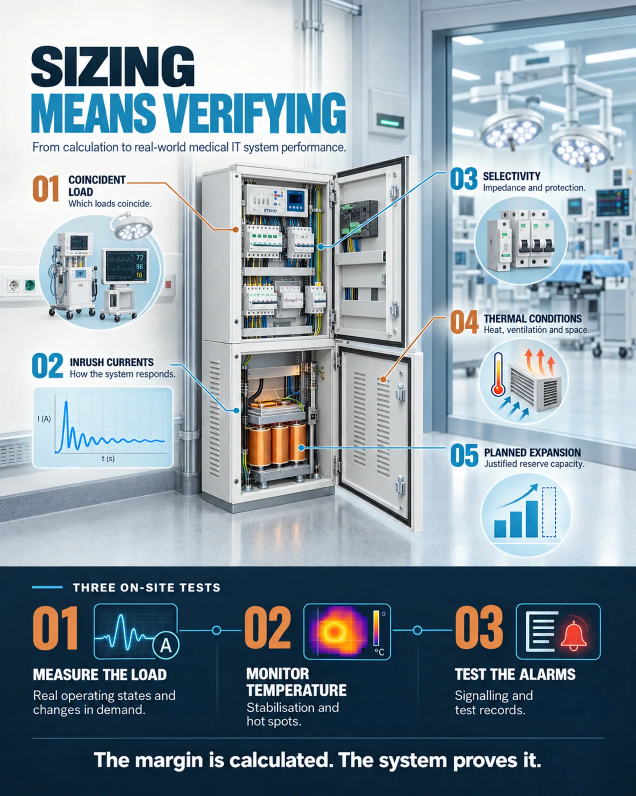
Sizing a medical isolation transformer is not simply a matter of adding up the rated power of every connected device and choosing the next size in the catalogue. The right choice must answer a more demanding question: which loads can realistically operate together, how will the system respond to transients, and how much thermal headroom will the assembly retain under its actual installation conditions? In a medical IT system, the answer affects continuity of supply, protection coordination and the ability to detect deterioration before it becomes an incident.
The power rating is therefore only the starting point. The design must bring together the clinical equipment inventory, operating profiles, inrush currents, panel ventilation, ambient temperature and reasonably foreseeable expansion. Commissioning must then demonstrate that those assumptions hold true. This approach avoids two opposite mistakes: choosing an undersized unit with no headroom, or oversizing without justification and increasing magnetising inrush current, space requirements, cost and the difficulty of coordinating protection.
Connected load is not the same as design load
An operating theatre may contain an operating table, imaging equipment, monitors, pumps, endoscopy towers, electrosurgical units, integration systems and sockets reserved for mobile equipment. However, not all these devices draw their nameplate power at the same time or for the same duration. The design load must be based on representative clinical scenarios, not an indiscriminate total.
The first step is to classify each device by its operating pattern:
- Continuous loads: remain connected for almost the entire period of activity and form the baseline load.
- Simultaneous loads: can reasonably be expected to operate together during a particular procedure.
- Intermittent loads: operate in cycles and must be assessed for both RMS current and cumulative heating effects.
- Loads with starting or switching transients: may cause voltage drops or protective device trips even when their steady-state demand is modest.
- Spare capacity: covers identified, documented extensions rather than a percentage added automatically.
The useful outcome is not a single figure but a range of scenarios: normal operation, the highest credible demand during a procedure, connection of a significant load, and operation under degraded conditions or during maintenance. For each scenario, record the apparent power, current, power factor, duration and expected frequency. Where equipment incorporates power electronics, it is also prudent to consider harmonic content and the actual current waveform, because two loads with the same nominal volt-ampere rating do not necessarily produce the same heating.
Power rating, inrush current and impedance: three connected decisions
Selecting an adequate power rating is essential, but it does not guarantee reliable performance on its own. The transformer is part of a system: upstream are the supply and a protective device; downstream are final circuits and clinical equipment; around it is an enclosure with specific thermal conditions. Changing its rating can alter no-load current, inrush current, impedance and the energy available under fault conditions.
Magnetising inrush current deserves particular attention. It occurs when the transformer is energised and depends, among other factors, on the point in the voltage cycle at which switching takes place, residual flux and construction. It may be brief, yet still cause an incorrectly selected protective device to trip. The answer is not simply to increase the device rating: the trip curve, conductor cross-section, breaking capacity and overall selectivity must be checked for compatibility.
Impedance also affects voltage drop and short-circuit currents. Higher impedance can limit current, but may also increase voltage variation with load; lower impedance can place greater demands on protective devices. The appropriate value is determined as part of the installation study, not in isolation. The product standard IEC 61558-2-15:2022 sets particular requirements for isolation transformers supplying medical locations, but equipment compliance does not replace system calculations or the national installation rules applicable to the project.
Thermal headroom must be designed before it can be measured
Insulation life is closely linked to temperature. Losses in the windings and core generate heat, which must be dissipated in an environment where space is often limited. Even a correctly selected transformer can run hotter than expected if the panel has insufficient air inlets, other equipment adds heat, ventilation grilles become obstructed or the room temperature exceeds the design assumption.
The thermal assessment must cover the equipment, its enclosure and the room. Relevant factors include clearances from walls and components, natural airflow paths, the proposed ventilation, access for inspection and the avoidance of pockets where heat can accumulate. Altitude should also be reviewed where relevant, as it can affect cooling and insulation performance. Any correction factors or derating specified by the manufacturer must be included in the calculations.
The following matrix helps turn general assumptions into evidence that can be verified:
| Design input | Evidence required | Risk if omitted |
|---|---|---|
| Load profile | Measurements or validated clinical scenarios | Overloading or oversizing |
| Inrush currents | Equipment data and functional testing | Nuisance tripping |
| Impedance and protection | Coordination and voltage drop study | Lack of selectivity |
| Thermal environment | Temperature, ventilation and panel layout | Accelerated ageing |
| Planned expansion | Approved expansion plan | Assumed or insufficient spare capacity |
How to provide useful spare capacity without oversizing
Spare capacity must be linked to a specific need. This might be equipment awaiting procurement, a new clinical service or a defined number of future sockets. If expansion is uncertain, the clearer approach is to document the capacity available and the review required before any new loads are added.
A generic percentage can conceal two problems. If it is too small, it may not cover the critical combination of loads; if it is too generous, it can lead to a larger transformer than necessary and complicate protection. Electrical spare capacity is also of little use if the panel lacks adequate space, ventilation, terminals and circuits. The transformer’s capacity must be consistent with the physical and functional capacity of the distribution system.
The best margin is not the largest: it is one that is justified, measurable and preserves system coordination.
Integrating the transformer into the medical IT panel
The finished installation must be considered as an assembly. The transformer is integrated with protective devices, the insulation monitoring device, alarm indication and outgoing circuits. Separating the power compartment from control components makes maintenance easier and reduces exposure during inspection. A ventilated enclosure with clear cable routes and sufficient front access improves both thermal performance and maintainability.
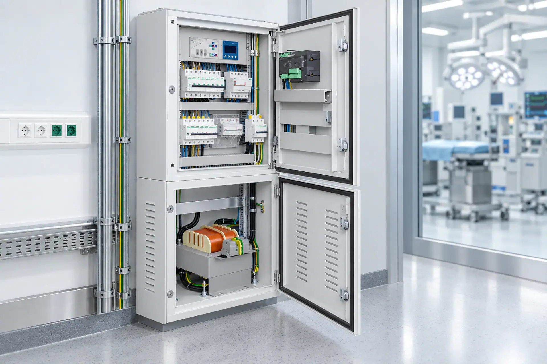
For single-phase applications, the ETKM TRM8 is a specific example of an isolation transformer for medical use. Its technical data sheet should be reviewed alongside the panel schematic, required rating and actual installation conditions. As with any product documentation, the edition of the standard cited in a data sheet and the compliance requirements of the project must be confirmed during specification and procurement.
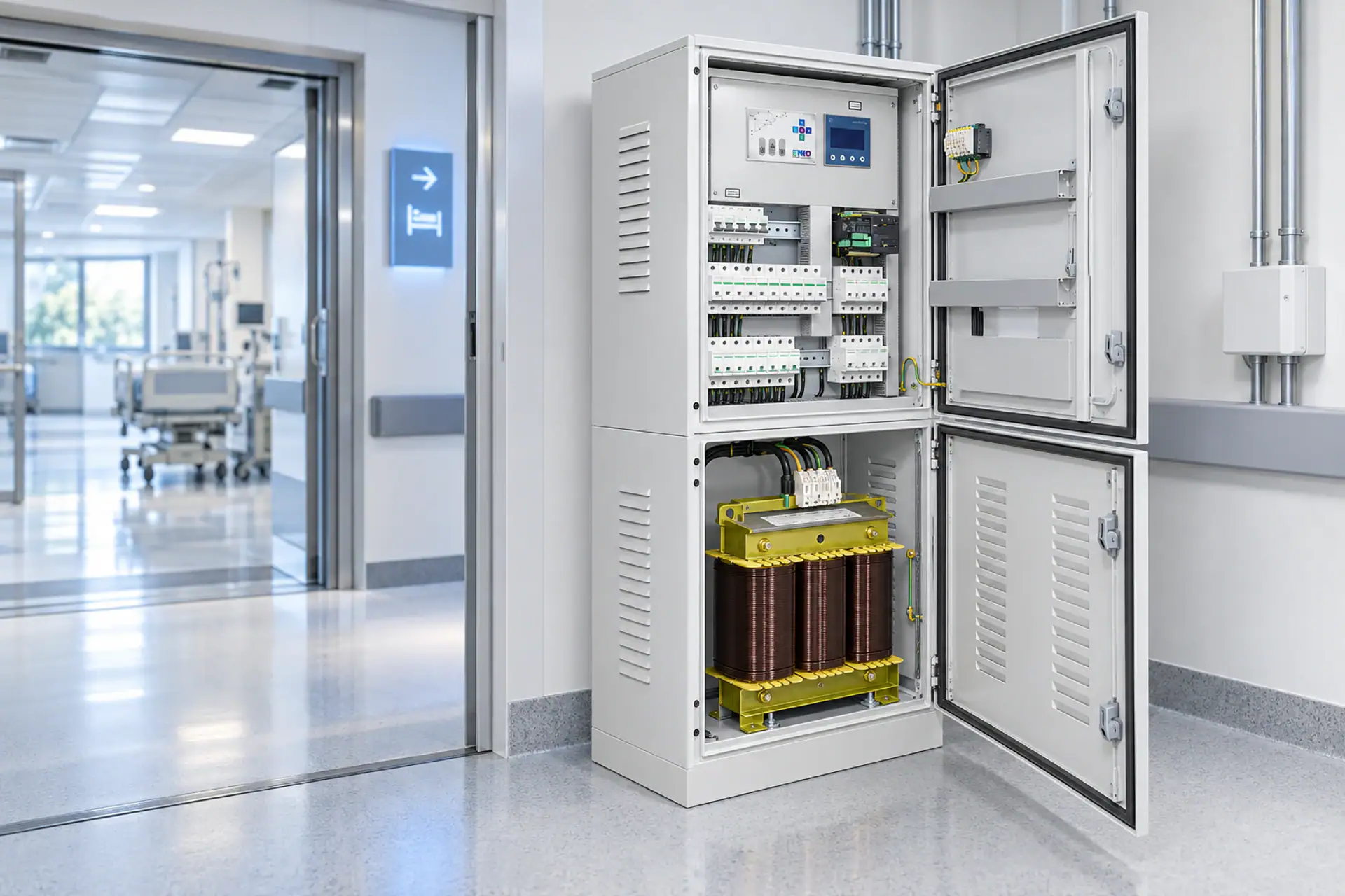
Where the electrical architecture requires a three-phase solution, the ETK TRT8 offers a different configuration to consider. The choice between single-phase and three-phase solutions should not depend on aggregate power alone: installation topology, the loads served, phase balance, protection and the requirements of the country and healthcare facility all play a part.
ETKHO develops transformers and solutions for medical IT systems that can form part of a complete engineering design. The value of this integration lies in coordinating equipment, panels, monitoring, alarms, documentation and testing from the outset.
On-site verification: demonstrating actual performance
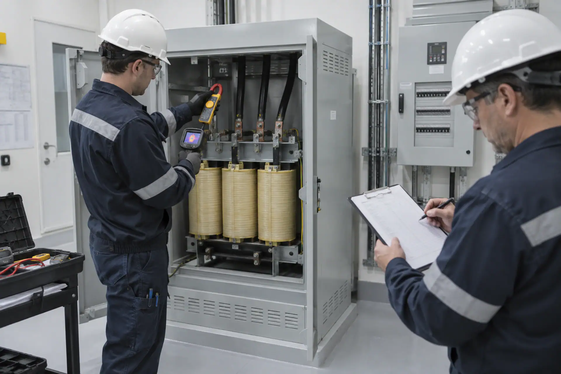
Commissioning must turn calculations into evidence. Before energisation, checks cover identification, connection tightness in accordance with the applicable instructions, protective conductor continuity, circuit separation, ventilation and consistency between drawings and the installed assembly. Progressive functional tests follow, without turning the exercise into an artificial loading arrangement that does not represent clinical use.
- Record the initial conditions. Ambient temperature, supply voltage, protective device status and connected equipment.
- Measure at no load and under load. Voltage, current, apparent power and any other variables specified in the test plan.
- Reproduce representative scenarios. Include relevant load changes and switching events authorised by the facility.
- Observe the temperature trend. A single snapshot is not enough: the aim is to establish whether temperatures stabilise and where hot spots develop.
- Test monitoring and alarms. Verify local indication, remote indication where provided, event identification and recording.
- Complete the traceability record. Retain details of the instruments used, date, responsible personnel, conditions and acceptance results.
Thermal imaging is useful, but it must be interpreted in context. An image without information on load, ambient temperature and operating time can lead to incorrect conclusions. It does not replace electrical measurements or checks on connection tightness and ventilation. Its value increases when surveys are repeated under comparable conditions so that trends can be identified.
Define acceptance criteria before testing
The test plan must specify in advance which values will be measured, for how long, and which deviations require testing to stop or further investigation. Agreement on these points prevents retrospective interpretation of the data simply to justify the outcome. Responsibilities must also be assigned: who authorises the test load, who monitors clinical conditions, who records alarms and who signs off completion.
If a variable has no directly applicable limit in the relevant standards, assessment can draw on a documented baseline, manufacturer information or approved design criteria. The important point is to state the basis. A temperature difference or voltage drop is not assessed by magnitude alone, but in relation to load, ambient conditions, duration and comparison with equivalent components. When testing reveals a deviation, the report must specify the action, the person responsible and the required retest; leaving an open observation is not enough.
The UK guidance document HTM 06-01 provides a practical framework for the design, verification and operation of healthcare electrical services. It does not replace Spanish regulations or project specifications, but it is a useful supplementary technical reference for structuring responsibilities, tests and documentation.
Common mistakes to identify during review
- Adding up all nameplate ratings without assessing simultaneous demand. This produces a large figure, but not necessarily a representative one.
- Applying a fixed margin without justification. Spare capacity should address an identified expansion requirement or uncertainty.
- Ignoring inrush current. This can cause trips that are wrongly attributed to insufficient transformer capacity.
- Selecting protection independently. The transformer, conductor and protective device must be coordinated.
- Accepting temperature performance on a single reading. What matters is the trend towards a stable state under a known load.
- Assuming catalogue ventilation conditions apply on site. Performance depends on the panel and room as installed.
- Failing to update the documentation. New clinical equipment can change simultaneous demand assumptions and require a system review.
From calculation to a maintainable installation
A medical isolation transformer is correctly sized when the selected rating, electrical coordination, thermal arrangement and test plan are consistent with one another. That consistency is more valuable than a large nominal margin. It establishes what can be connected, which behaviour is acceptable, which alarms should operate and when a trend requires intervention.
The final documentation should retain the load inventory, design scenarios, single-line diagram, protection settings and curves, environmental conditions, thermal results and alarm tests. Maintenance teams can then compare future performance with a reliable baseline and assess any proposed expansion before it is carried out.
Frequently asked questions
How is the required power rating of a medical isolation transformer calculated?
Start with an equipment inventory and develop operating scenarios that distinguish continuous, simultaneous and intermittent loads, as well as loads with inrush currents. Add justified spare capacity, then check voltage drop, protection, impedance and thermal conditions. Adding up nameplate ratings alone does not describe actual operation.
Is oversizing recommended to avoid problems?
Not indiscriminately. A larger unit can increase space requirements, cost and magnetising inrush current, as well as alter protection coordination. The margin should be linked to an identified expansion requirement or documented uncertainty and checked alongside the panel, ventilation and protective devices.
How does panel temperature affect performance?
Temperature affects insulation ageing and operating headroom. Ambient conditions, ventilation, clearances, heat from other components and possible obstructions must be reviewed. Verification should track the temperature trend under a known load, not rely on a single reading.
What should be checked during commissioning?
At a minimum, check conformity with the design, connections, protection, ventilation, voltages and currents under representative conditions, temperature trends, insulation monitoring operation, local and remote alarms, and the traceability of instruments and results. The final scope depends on applicable regulations and the facility’s test plan.
When should transformer sizing be reviewed?
Review sizing when clinical loads change, equipment is added, simultaneous demand scenarios change, unexpected trips or abnormal temperatures occur, or panel or room ventilation is modified. The assumptions should also be reviewed during refurbishment and before using the planned spare capacity.
Does IEC 61558-2-15 define the entire medical IT installation?
No. It is a product standard with particular requirements for isolation transformers supplying medical locations. The complete system design must also address applicable installation and safety rules, protection coordination, the facility’s design requirements and those of the competent authority.
Transformer sizing backed by measurements
If you need to review the expected load, coordinate protective devices or assess the thermal headroom of a medical IT panel, consult ETKHO’s technical advisory service to define the solution and its verification plan.