
In this article, we would like to address the more technical side of some of the best electrical safety solutions for hospitals and their critical areas. This is the case of TN electrical systems. We will discover what they consist of, what differentiates them from other TT systems and we will delve into the virtues of TN-S networks for electrical installations in hospitals.
What are grounding connections?
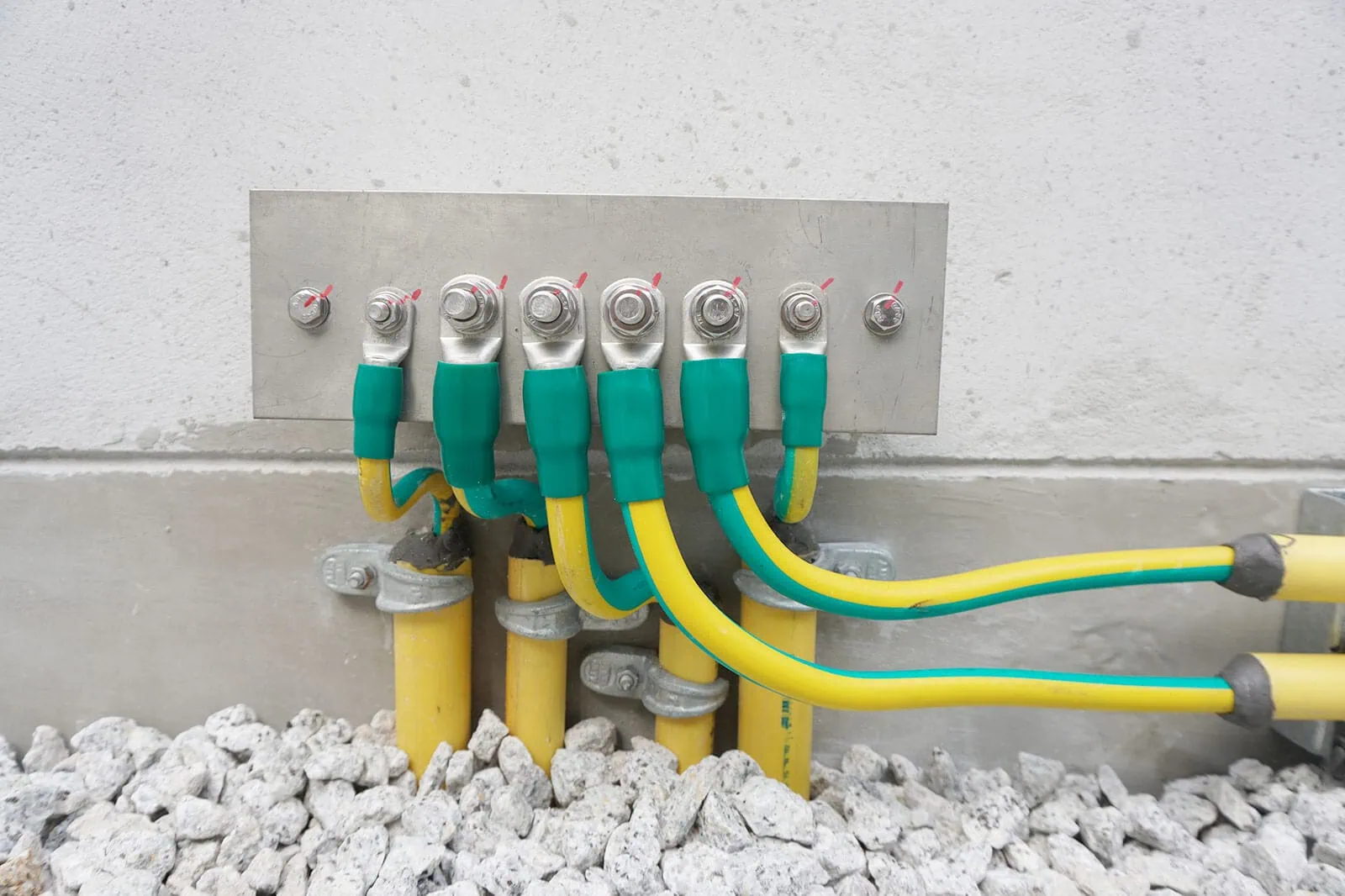
Connectors and sockets are key to creating an equipotential bonding to the ground, which helps to avoid touch voltages in critical medical areas.
Therefore, equipotential grounding is an elementary part of safe electrical installation for critical medical environments. These ground connections systems are suitable for surgical units, ICU and in general for critical medical areas.
Thus, electro-medical equipment and exposed conductive surfaces within critical medical areas must be connected to an equipotential ground, with a connector with a highly flexible conductor of sufficient cross-section.
What is their purpose?
Ground systems facilitate safety functions by providing the electrical installation with a low impedance path for any faults in the electrical network. Grounding in turn acts as a reference point for the electrical supply and safety devices to function correctly.
Types of ground connections
Grounding configurations can be arranged in different ways on the supply and load side but always achieve the same result. It is the international standard IEC 60364 (Electrical installations for buildings) that identifies three families of grounding, which are defined by a two-letter identifier in the form ‘XY’. ‘X’ defines the neutral and ground conductor configuration on the supply side of the system (generator / transformer), and ‘Y’ defines the neutral / ground configuration on the load side of the system (main switchboard and connected loads).
X’ and ‘Y’ can take the following values:
T – Ground (from the French ‘Terre’).
N – Neutral
I – isolated
And subsets of these configurations can be defined using the values:
S – Separate
C – Combined
“According to the various protection methods and terminologies defined by IEC, low voltage power distribution systems are divided into three types according to the different grounding methods, namely TT, TN and IT systems.”
IT system
Here all active conductors are separated from ground or one point is grounded with an impedance. This means that, in the event of an insulation fault, only a small fault current can flow, mainly due to the shunt capacity of the network.
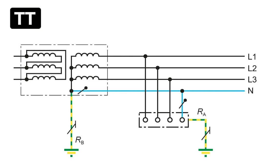
TT system
The TT method refers to a protective system that directly grounds the metal enclosure of an electrical device, which is called a protective grounding system. With a TT configuration, each area employs its own grounding within the facility, independent of any grounding on the source side. This type of grounding is generally used in situations where a distribution network service provider (DNSP) cannot guarantee a low voltage connection to the power supply.
TN Grounding System
A TN mode power supply and protection system that connects the metal enclosure of electrical equipment to the working neutral wire. It is called a zero protection system.
Thus, when a single point on the source side is directly connected to groundi we speak of a TN grounding system. Any electrical equipment connected to the system is grounded through the same connection point on the source side. These grounding systems require grounding electrodes at regular intervals throughout the installation.
TNs house three sub-assemblies, varying according to the method of segregation/combination of neutral and ground conductors.
TN-C
The functions of the neutral conductor and protective conductor are combined in a single conductor throughout the system. TN-C describes an arrangement where a combined protective neutral (PEN) is connected to ground at the source. Thus, it uses the working neutral line as the zero-crossing protective line, which can be referred to as the protective neutral line and can be represented by PENs.
TN-CS
In one part of the system, the functions of the neutral conductor and the protective conductor are combined in a single conductor. The supply side of the system uses a combined PEN conductor for grounding, and the load side of the system uses a separate conductor for PE and N.
TN-S
A separate protective conductor is used throughout the system. Separate conductors are run for protective ground (PE) and neutral to the consumer loads from the power supply at one location (i.e. generator or transformer). In this case, the PE and N conductors are separated in almost all parts of the system and are only connected to each other at the supply. In this way, the power system in TN-S mode strictly separates the working neutral N from the dedicated protection line PE. Let us now take a closer look at some of its features, which make it stand out and make it the leading system in hospital electrical installations.
“The power system in TN-S mode strictly separates the working neutral N from the dedicated protection line PE.”
Características del sistema TN-S
- Protection conductors. It has a single potential reference “source” and “use”. In addition, it does not use ground as a conductor.
- Equipotentiality. The ground have good equipotentiality, which implies a very relevant cost saving as it is not necessary to install complementary equipotential connections.
- Low impedance. The protection circuit is low impedance as there is no need to conduct significant drain, fault or short-circuit currents.
- Commitment to EMC regulations. It is widely recognised in the electrical industry that the TN-S system is the most committed to EMC (Electromagnetic Compatibility Regulations).
What is the difference between TT and TN-S systems?
As we can see, in a grounded network with a TN-S or TT system, one or more points of the network, the installation or the electrical equipment are grounded to guarantee electrical safety.
However, in TN systems, the neutral point of the supply transformer is grounded with a negligible impedance and the electrical installation grounds are connected to the service ground of the network by means of a protective conductor. However, in TT systems, although the neutral point is also grounded with negligible impedance, the electrical installation grounds are grounded separately from the system ground.

Benefits of the TN-S system
Despite the higher initial investment for installation and material costs, and the subsequent maintenance of the power lines, the benefits of TN-S are such that it is more than justified as an grounding system:
1. It grants a higher degree of electrical fire safety
With TN-S, we can use protective shutdown devices (RCDs) in the optimum mode. An RCD connected to an electrical network with a TN-S ground circuit disconnects the power supply to the faulty consumer as soon as leakage currents occur.
2. It does not create problems to create and monitor the technical condition of the grounding circuit of the object
Since the grounding loop requires constant monitoring, under the influence of weather and natural factors the device may fail. This will lead to disruption of electrical systems and, more importantly, becomes a threat to health.
3. No need to use jumpers connecting the metal casings of medical devices and equipment to the ground loop
This helps us to avoid inconvenience and aesthetic defects of the interior of the room or area, promoting holistic view of health.
4. Eliminates high frequency interference
This induces detrimental effects on the functioning of electronics.
At ETKHO we help you choose
As experts in engineering and electrical installation solutions for hospitals, at ETKHO we analyse each client’s case in a personalised way to guide them and ensure their healthcare installations with the most optimal systems for the present and the future. If you have any doubts or are looking for advice on the electrical installation for your hospital, do not hesitate to contact us.

ETK EES. Ground connections for medical use
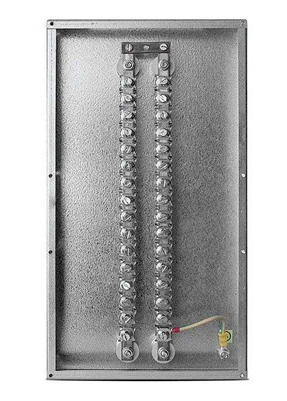
ETK EBB. Busbar plate for equipotential connections